Friday 10 February 2017

ROBOTICS: Compiling the 7Bot Arduino code for the ESP8266 - BangBot

I wrote previously about building a desktop robot arm that I started calling the BangBot (because I bought it from bangood). I finished with a brief overview of the existing open source software solutions including some software written for similar desktop robots. 
In this post I'll investigate the specifics of the 7Bot software written for a similar looking desktop bot. 


7Bot Software:

The software comes in two components:
  • Arduino code to run the robot
  • Desktop code that passes positions to the robot and includes a simulator/visualiser. 

I'll be focussing on the embedded software that controls the arm over serial communications. You can find more info on the serial communications protocol here.

I forked the github repo of the 7Bot Arduino software which has been written specifically for the Arduino Due. This board has some special features that your run-of-the-mill Arduino has like a 12 bit DAC on 12 channels and high clock speed.

As this isn't a typical feature of low cost Arduinos I'm pretty sure I'll end up needing an external servo driver board, but until I hit a wall I'll try to get everything running off the one board.

My gut feel is that I'll want to use a board with some decent clock speed to make sure the Inverse Kinematics equations are computed quickly enough to give smooth robot motions when operating in Cartesian mode. This is because the robot needs to interpolate the path between points and calculate do the IK calculations to update joint angles at at least 15fps for smooth motion.
For this reason I'm going to try to get it compiling for an ESP8266 as the base clock speed is 80MHz and is capable of going up to 160MHz. I'll need to do some research to understand how this clock speed relates to real world computational speed and how that compares to the Due.


Embedded Device Specs:

I need to compare the ESP8266 with the Due to understand how it might handle the code designed for the 7Bot and the Due board:

ESP8266
  • IEEE 802.11 b/g/n Wi-Fi
  • 32-bit RISC CPU (80 or 160MHz)
  • 64 KB of instruction RAM, 96 KB of data RAM
  • External QSPI flash - 512 KB to 4 MB* (up to 16 MB is supported)
  • 16 GPIO pins
  • 1 10-bit ADC (analog input pins)
  • UART on dedicated pins, plus a transmit-only UART can be enabled on GPIO2

Arduino Due
  • 32-bit ARM core (84 MHz)
  • 96 KB (two banks: 64KB and 32KB)
  • 512 KB all available for the user applications
  • 54 (of which 12 provide PWM output) 
  • 12 12-bit ADC (analog input pins)
  • 3 UARTs

I found that there were already some basic benchmark comparing some basic operations of the ESP and the Due on the Arduino forums:

BENCHMARK RESULTS (smaller values are better):

ESP8266 @160MHzArduino Due @84MHz
float [ms]216636
int [ms]2828


Code Changes

As I was making my changes I found that some changes were pushed to the main repo that allowed for more typical flash storage using the EEPROM library. First problem solved.

In order to get the project to compile I also needed to change the analogWriteResolution function to the analogWriteRange function available on the ESP8266. I've not yet tested this at PWMRANGE 4096.

The last issue I overcame was a compiler optimization issue that was giving me a linkage error:
xtensa-lx106-elf-gcc: error: libraries\Arm7Bot\Arm7Bot.a: No such file or directory

xtensa-lx106-elf-gcc: error:
Solved this one by commenting out the dot_a_linkage=true line in the library.properties file.
The software now compiles for an ESP8266, now to get in to the testing.


Monday 6 February 2017

ROBOTICS: Desktop six axis robot arm - BangBot

Desktop robot arms have been generating of lot of Kickstarter excitement lately offering folks a chance to dabble in the art of hobby robotics without making a significant investment. I've been following them for a while and while the cost is definitely coming down, they are still typically start at around 300USD.

There are a few open source desktop robot arm kits that have been through Kickstarter, here are a couple of my favorites:


uArm 4 axis robot arm


7Bot 6 Axus robot arm

As with most of the good open source stuff the Chinese manufacturers seemed to have jumped on the bandwagon and started to manufacture replica kits and knockoffs. You can typically pick up a good knockoff bargain on sites like AliExpress or Bangood


Hardware:

Recently I came across this mini desktop robot arm on bangood.com that uses hobby servos to create a six degrees of freedom robot arm. As I've seen with a robot hexapod I bought from AliExpress based off the Lynxmotion Phoenix hexapod, the hardware kit will most likely be a slight variation of the original and offer no software support. 

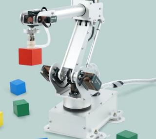
BangBot knockoff of the 7Bot
I've got a few servos knocking about from some old projects so for the most part I should be set, but as I've seen with other projects it's probably going to pay off to have a powerful digital servo down the bottom of the kinematic chain. With serial link robots the joint at the bottom off the robot will be carrying the most load so I thought it would be wise to invest in something a little more powerful than I had lying around. I went for the PDI-6221MG digital servo from Bangood with 20kg/cm at 6v.


Software:

I'm not expecting any software support so while I wait for the kit to arrive in the mail I've started to investigate any open source software solutions rather that starting from stratch with my own. There are a few packages out there, but seeing as the hardware is most similar to the 7Bot I thought I would start there.

The most important info when trying to match the existing software to this robot is the way the joints are oriented on the robot. Simply saying that the arm is six axis isn't enough, we need to know joint lengths and actuator location and orientations to make sure the inverse kinematics are compatible.


Serial link kinematic chain


The 7Arm robot seems closest in design to the BangBot robot arm so this seemed like a good starting place for the software.

Taking a look through the code it seems as though the Inverse Kinematics (IK) parameters aren't hard coded so it should allow me to make some minor changes to joint parameters and get the software up and running. I won't go through the specifics of generating a set of inverse kinematic equations for a robot arm, but if you want to read more on the topic take a look at the pages here.

At the moment my biggest issue with compiling the code is my lack of Arduino SAM (32-bit ARM Cortex-M3) boards lying around, so I'll have to try to convert the code to run on a more conventional Arduino device. A the moment I'm thinking maybe the ESP8266 could be a good fit as it is also a 32 bit MCU and has a 160MHz clock frequency as well as EEPROM storage. I'll see how I go making the port, I may need to include a servo control board if the ESP8266 can't handle the task, I've never attempted any servo control with the ESP8266.

Thursday 2 February 2017

DRONE: Safe LiPo Charging

I've owned a few toys with Lithium Polymer batteries in the past and never really been aware of the risks associated with charging the things until recently. I've heard of LiPo fires and seen the YouTube videos but only ever associated the mishaps with improper use. It wasn't until I got in to racing quads and had my first big crash that I though of 'improper use' and that I could be putting myself and family unnecessarily at risk by charging them in the corner of my lounge room.

There are number of places you can read up on LiPo battery charging safety including safe storage, here are my favorites.

The main points:

  1. ***Visually inspect batteries after a crash. DO NOT CHARGE DAMAGED CELLS***
  2. Charge on a non combustible surface (concrete floor works well)
  3. Charge LiPos in a fireproof container such as a LiPo storage bag or ammo tin
  4. Stop charging after you batteries are fully charged
  5. If you lipo catches fire make sure you don't breath the toxic fumes, so charge in a well ventilated area
  6. Store LiPo batteries at safe storage voltage to prevent possible damage to cells
Really the most important thing to remember is not to charge damaged cells. This includes cells that have been punctured, dented or even batteries that have puffed up. This is the biggest thing you can do to prevent a LiPo fire.

To cover points 2 and 3 most American sites suggest an ammo tin as a good storage area but these are hard to come by in Australia, so I got creative and came up with my own solution:

Discharging LiPo batteries for safe storage

Charger mounted to outside of the charge box


I converted a cash box to charging/discharging box to hit points 2,3 and 6.
I haven't had a lipo fire (yet) so this solution isn't tested, but it goes a long way towards safety. 

Bill of Materials:

Total spend was a little over $45

I now charge my batteries in the garage and use the power timer set to 4h to hit points 3 and 4. Although it's not a perfect setup to stop charging the batteries after they are full it's definitely going a long way towards safe charging of my LiPo batteries.


Update: 

I'm trying to come up with a way to use a power monitor that turns off the point once it sees a minimum power consumption coming from the socket. I'm experimenting with a Belkin WeMo Insight device that seems to look promising, although it's not the most cost effective device at $70 a pop. This should get me another step towards safe charging of my LiPo batteries.

HOME AUTOMATION: ESP8266, Blynk and OTA Updates

I previously used Blynk to set up remote access to my house via my phone and a electric door strike. Since then I learned of the Arduino Over The Air (OTA) update library that would allow me to remotely update the firmware of my device so naturally I immediately wanted to add this feature.

Arduino OTA Library:

You can read about the library on the Arduino github site here, but basically there are three ways you can implement the OTA update:

  1. Arduino IDE
  2. Web Browser
  3. HTTP Server
I've decided to go for the Arduino IDE scenario that is described here.
The requirements for this process are:
  • Arduino IDE (tested with 1.6.8)
  • Python 2.7


Arduino IDE OTA Update:

Basically all you really is the command "ArduinoOTA.begin();" in the setup routine and the command "ArduinoOTA.handle();" in the loop function. This is the bare minimum you need to get it working, but we'll add some more things like error handling and some basic security.

EDIT: I couldn't get the Arduino IDE security feature working on my windows 10 machine, it seems there are a few bugs still being worked out 


Blynk and OTA Code:


/**************************************************************
 * Blynk is a platform with iOS and Android apps to control
 * Arduino, Raspberry Pi and the likes over the Internet.
 * You can easily build graphic interfaces for all your
 * projects by simply dragging and dropping widgets.
 *
 *   Downloads, docs, tutorials: http://www.blynk.cc
 *   Blynk community:            http://community.blynk.cc
 *   Social networks:            http://www.fb.com/blynkapp
 *                               http://twitter.com/blynk_app
 *
 * Blynk library is licensed under MIT license
 * This example code is in public domain.
 *
 **************************************************************
 * This example runs directly on ESP8266 chip.
 *
 * WARNING! ESP8266 SSL support is still experimental.
 *          More info here: https://github.com/esp8266/Arduino/issues/43
 *
 * Note: This requires ESP8266 support package:
 *   https://github.com/esp8266/Arduino
 *
 * Please be sure to select the right ESP8266 module
 * in the Tools -> Board menu!
 *
 * Change WiFi ssid, pass, and Blynk auth token to run :)
 *
 **************************************************************/

#define BLYNK_PRINT Serial    // Comment this out to disable prints and save space
#define RELAY_PIN D1

#include <ESP8266WiFi.h>
#include <BlynkSimpleEsp8266_SSL.h>
#include <Ticker.h>
#include <ArduinoOTA.h>

// You should get Auth Token in the Blynk App.
// Go to the Project Settings (nut icon).
char auth[] = "XXXX";

// Your WiFi credentials.
// Set password to "" for open networks.
char ssid[] = "XXXX";
char pass[] = "XXXX";
char hostOTA[] = "DoorLock";
char passOTA[] = "XXXX";

bool vPinState = false;               // Set the default virtual pin state
int maxRelayOnTime = 10;              // Set the max on time of the relay 
int minRelayOnTime = 1;               // Set the minimum on time of the relay
int vDelayTime = minRelayOnTime;      // Set the initial delay time value
Ticker doorLatch;                     // Callback fuction instance

void setPinLow()
{
  digitalWrite(RELAY_PIN, 0);
  doorLatch.detach();
}

void setup()
{
  Serial.begin(9600);
  Blynk.begin(auth, ssid, pass);

  pinMode(RELAY_PIN, OUTPUT);
  digitalWrite(RELAY_PIN, 0);

  ArduinoOTA.setHostname(hostOTA);
  //ArduinoOTA.setPassword(passOTA);
  ArduinoOTA.onStart([]() {
    Serial.println("OTA: Start");
  });
  ArduinoOTA.onEnd([]() {
    Serial.println("\nOTA: End");
  });
  ArduinoOTA.onProgress([](unsigned int progress, unsigned int total) {
    Serial.printf("Progress: %u%%\r", (progress / (total / 100)));
  });
  ArduinoOTA.onError([](ota_error_t error) {
    Serial.printf("Error[%u]: ", error);
    if (error == OTA_AUTH_ERROR) Serial.println("OTA: Auth Failed");
    else if (error == OTA_BEGIN_ERROR) Serial.println("OTA: Begin Failed");
    else if (error == OTA_CONNECT_ERROR) Serial.println("OTA: Connect Failed");
    else if (error == OTA_RECEIVE_ERROR) Serial.println("OTA: Receive Failed");
    else if (error == OTA_END_ERROR) Serial.println("OTA: End Failed");
  });
  ArduinoOTA.begin();
  Serial.println("OTA: Ready");
}

void loop()
{
  ArduinoOTA.handle();
  Blynk.run();
}

BLYNK_WRITE(V0)
{
  // Get the virtual input state
  vPinState = param.asInt();

  // If the virtual input went high
  if(vPinState)
  {
    // Open the relay
    digitalWrite(RELAY_PIN, 1);
    // Turn off the relay after the defined delay time
    doorLatch.attach(vDelayTime, setPinLow);
  }
}

BLYNK_WRITE(V1)
{
  // Get the input from the virtual input slider
  vDelayTime = param.asInt();

  // Constrain the virtual slider input to within the preset bounds
  vDelayTime = constrain(vDelayTime, minRelayOnTime, maxRelayOnTime);
}


How to update your device OTA:

Once you get the code loaded on to your device you should see the unit appear in your list of ports under the 'Tools' heading.
I had to reboot my machine to get this to work for me. Now you can upload code to your device over the network as if it was connected via USB.